Boombox Briefcase W/ LED Equalizer Part 3

dpp

My briefcase boombox with equiliser display isn’t 100% complete yet but I decided to take it out to a party. Nobody noticed that some of the control knobs and sliders didn’t do anything yet. The event was Tom And Gary’s NYE Decentralized Dance Party. About 100 people and boomboxes showed up at a Skytrain station. Tom brought a power glove controlled pirate FM transmitter to broadcast audio to the boomboxes. We wandered around downtown for a while, took a skytrain to the airport, and made the newspaper.

Boombox Briefcase W/ LED Equalizer Part 2

IMGA0860IMGA0851

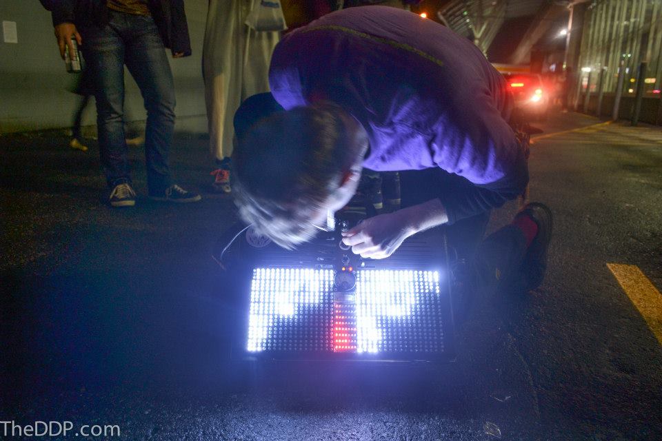
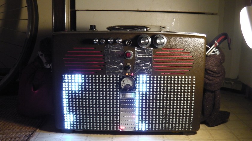
Progress on the Equalizer  LED Briefcase:

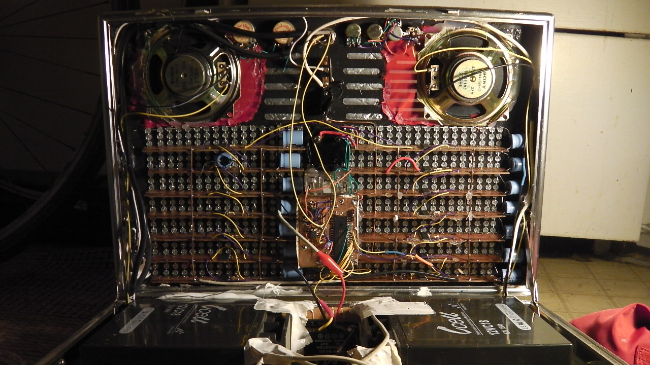
Speakers are installed. I’m using a pair of full range 4″ 30W RMS speakers salvaged from a broken stereo. They’re not a perfect match for the ovoid vent holes I cut for speakers, but some stretched red fabric hides it.

Batteries are installed. I’m using a pair of 12v 18Ah SLA batteries. Given the system’s average current draw of three amps this will last 12 hours. This is certainly overkill but with this much power to spare I can plug other equipment into the briefcase (very useful). It’s really heavy though. I might decide to take one of them out.

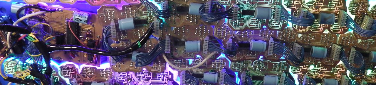
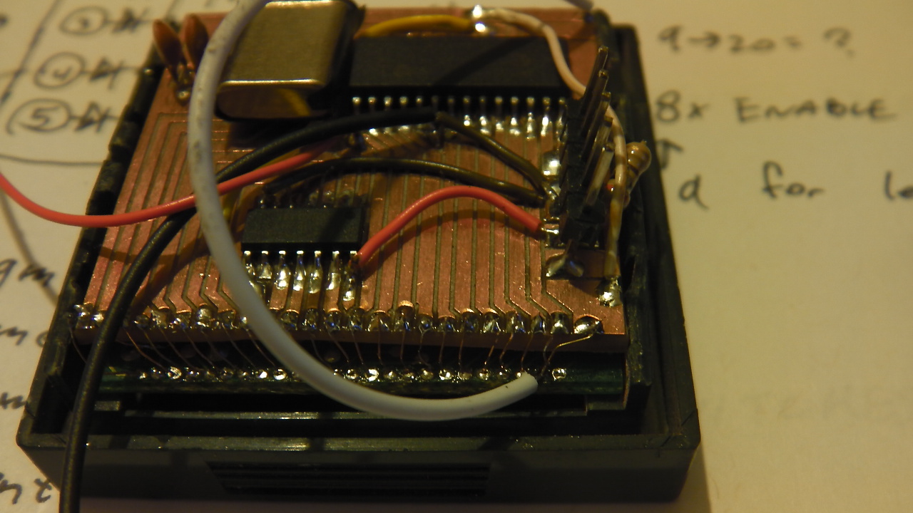
I decided to replace the PIC18F2620 with a PIC18F4550. Mostly because the little 2620 didn’t have a lot of IO pins and I didn’t want to go through the mess of trying to expand it with shift registers or latches.

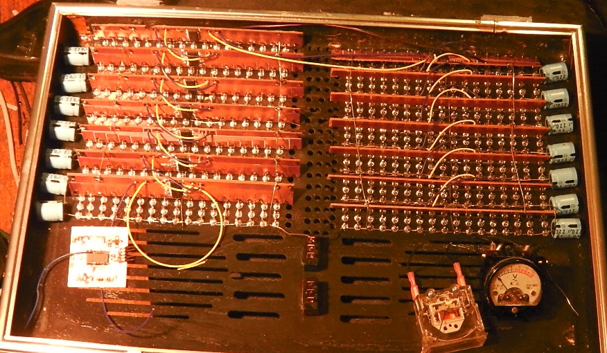
I still need to finish the analog equalizer control system.  The horizontal slots on the near the center top are for slide potentiometers to be used in this system.

There are also a few potentiometers that don’t go to anything. They will eventually run to the microcontroller ADC and used as inputs to control LED brightness, as well as the hysteresis and sensitivity of the audio response system.


Boombox Briefcase W/ LED Equalizer Part 1

IMGA0230


I found a very nice looking old briefcase at a thrift store today. I’ve decided to turn it into a boombox briefcase with an LED equalizer display as well as a pair of galvos and other assorted bells and whistles. So far I’ve built some boards,  CNC’d the briefcase, and started placing components.

The system is going to run off 12v because that’s the most common for stereo amp boards.

There are fourteen equalizer boards split into left and right. Each bar has seventeen stages. Each stage is made up of three 5mm 3v 20mA frosted white LEDs in series. LED bars are driven by WS2803 chips on some boards I’ve cut  and mounted at 90 degree angles. Audio processing will be done by a pair of MSGEQ7 chips. A PIC18F2620 reads their values through its ADC and controls the WS2803s through SPI.

I have a new fridge / component organizer.

IMGA0124

I moved into a new apartment today, and this one has a fridge. While packing up the old laboratory I realized I own hundreds of little bags of electronic components in random junk boxes.  As soon as I got to my new place I decided to get them organised. This was the result.

I’ve tried using those racks of small boxes for organizing parts like this, but pretty quickly most boxes contain items that don’t match the label I wrote on them. I think this is a much simpler and easier to maintain system. Resistors and capacitors are in grids with first digit assigning the column and ascending value assigning the row. ICs, connectors, and everything else are spread out fairly randomly in the remaining space.

Cyberpunk Watch Project part 6.

6

I put the finishing touches on my watch tonight including a case and strap:

The timer interrupt service routine is working properly and keeping perfectly accurate time.

The watch is being powered by half a 9v battery (AKA three 1.5v AAAA batteries). I estimate this will last it about a week.

It turns out the buttons and their diodes were designed to form a charlieplex button circuit. I have no idea why anyone would do this with only four buttons, but once I figured that out reading them made sense. The up and down arrows adjust the minutes or hours depending on if the index or enter key is being held down at the same time.

The project is completed for now but there is room for improvements. I could fit a PIN geiger counter in there and add a speaker for alarm clock type functionality. Driving a watch uses only a small power of the PIC18F2620’s processing power. I could have it synthesize speech  to make a talking watch; among many other things.

Cyberpunk Watch Project part 5.

5

The Electronics I designed worked perfectly, and I have the LED programming completed. The watch displays hours and minutes in the top red digits, seconds and centiseconds in the bottom green digits. Centiseconds show up as 88 in every picture due to my camera’s exposure time.  The watch is set up to do some basic counting at the moment. I still need get timer interrupts working properly so it keeps accurate time. Reading in the buttons is also still wonky. I really need to figure out what the purpose of those diodes around them is. The way they connect doesn’t form an OR gate like I had assumed. They also don’t appear to be any good for debouncing.

Cyberpunk Watch Project part 4.

4

Here I’ve soldered together the microcontroller board and mounted it on the display. The board is a PIC18F2620 driven by a 20Mhz crystal. A 74HC164 shift register is used to drive the LED matrix anodes since the PIC didn’t have enough output pins to do everything by itself.

The only crystal, capacitors, and resistors I had lying around were the big bulky through hole variety. I’ll replace these with smaller versions if I need more room for batteries.

Cyberpunk Watch Project part 3.

Watch 3

With a bit of trial and error I’ve managed to figure out the circuitry of the burner control panel. As I suspected the seven segment displays are common cathode and connected together in a matrix. Each cathode goes to one pin and each parallel group of segments goes to a pin.

There are four LEDs running up the left side of the display panel that I don’t fully understand. I know they must be hooked into the same matrix as the 7-segments but I can’t identify the pins they connect to.

The butons are also a little bit of a mystery. For some odd reason they have diodes connected to them. I suspect they’re being used as an OR gate so every button can trigger an interrupt on a microcontroller with a single interrupt pin. This means I can probably ignore it.

I’m probably getting a little ahead of myself but I’ve gone and designed a microcontroller PCB to sit behind the display panel. Hopefully I’ll be able to figure everything else faster once I can control the display through code.