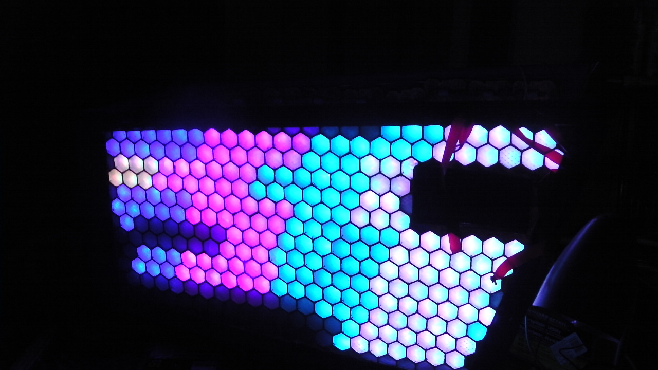
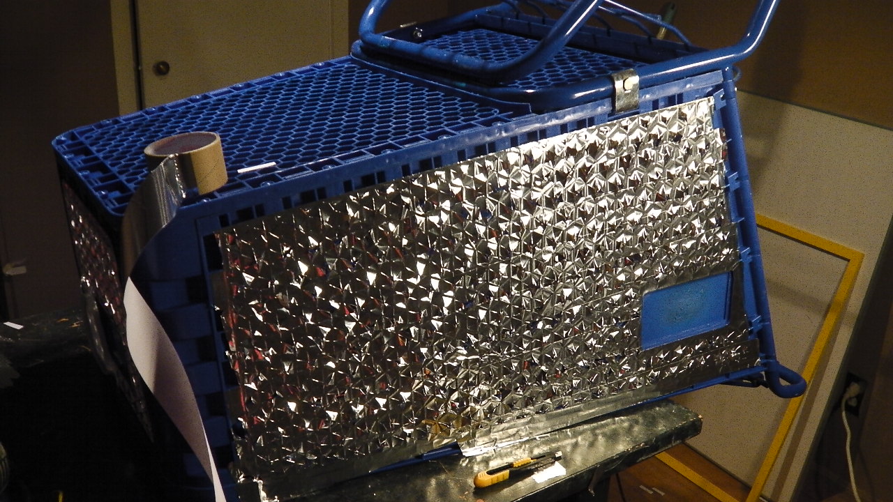
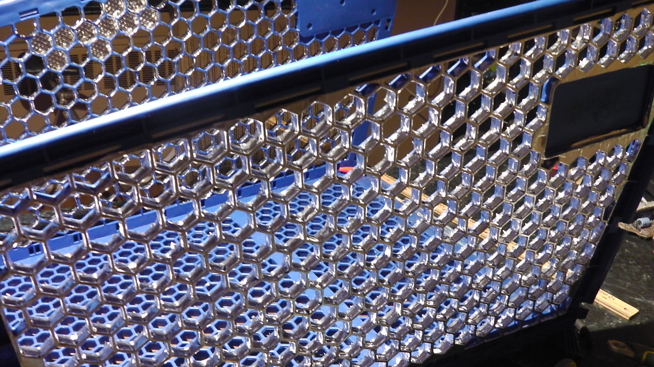
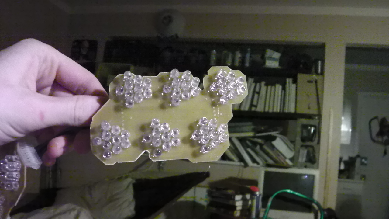
After prepping the shopping cart cage with shiny tape and diffusion it’s time to start installing the LED circuit boards.

After prepping the shopping cart cage with shiny tape and diffusion it’s time to start installing the LED circuit boards.
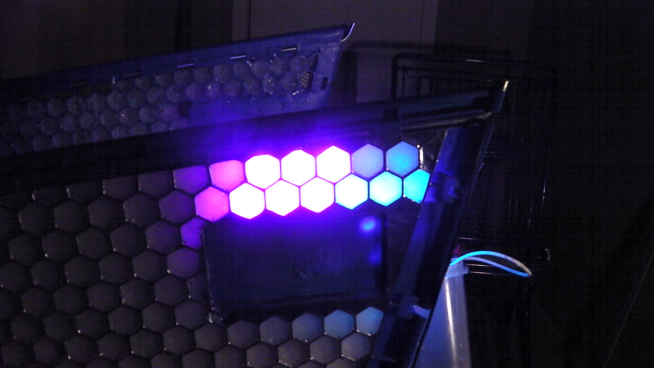
After adding shiny tape to the cart I started working on diffusing the LEDs. The circuit boards I designed don’t scatter the different colors LEDs out very much. It was a sacrifice I had to make in order to keep costs down with single sided copper clad boards. Diffusing will make blue and red produce purple, instead of two discrete spots of each colour.
This is a lighting diffuser panel from Home Depot. It’s the thing you see over the lights in a lot of office buildings. They gave it to me for free because it was broken!
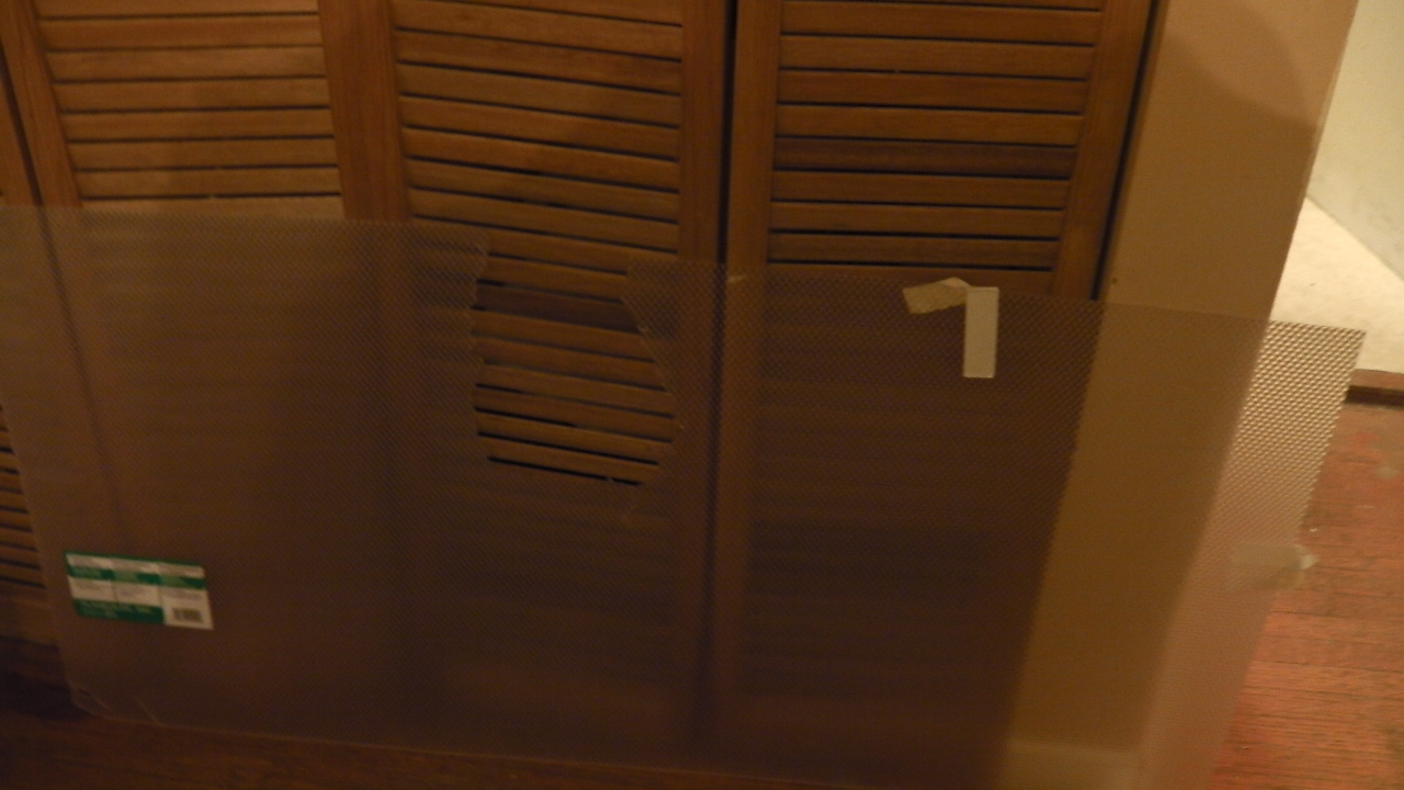
I used the CNC machine to cut the diffuser panel into hexagons to fit into the cells of the cart basket.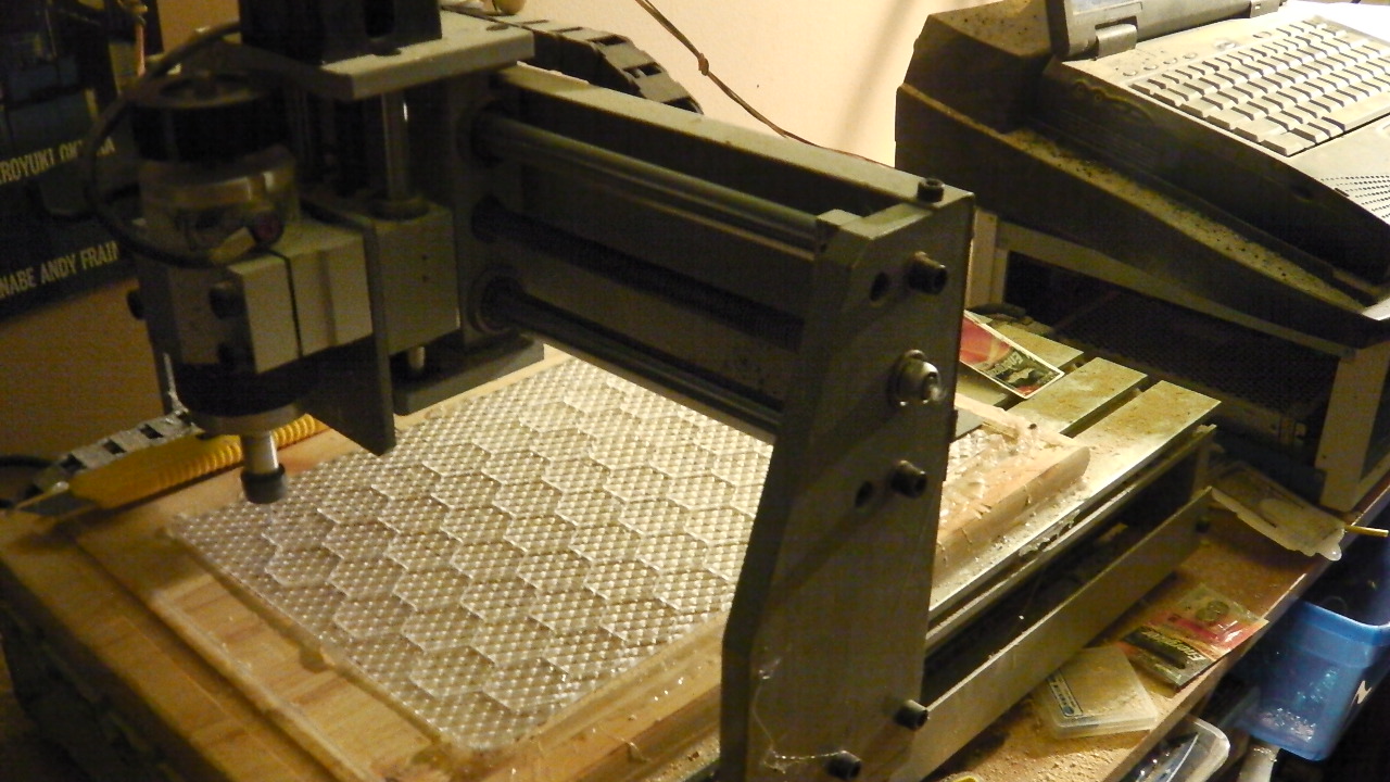
I inserted the hexagonal diffuser panels into the cart with a very liberal amount of clear acrylic. The acrylic will help diffuse the LEDs further,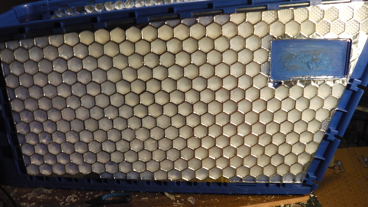
[April 2013]
I wanted to get a lot of the circuit boards done before carrying a rusty abandoned shopping cart back to my apartment. The landlord already think I’m a crazy person. I don’t think she would fully understand if I said “It’s for an art project, I just need to finish building circuit boards for it”.
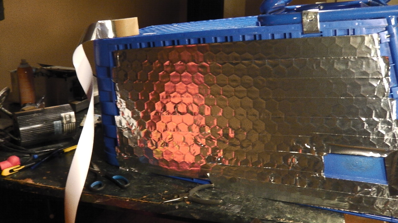
It was a dark blue shopping cart, so before installing the LED boards I decided to cover the cells with reflective aluminium tape. It will make the lights brighter.
[March 2013] I was at a rave Wreck beach last night and for some reason there was a shopping cart down there. It could be debris from the 2011 Japanese Tsunami. It was a plastic shopping cart with a hexoganal (honeycomb) basket. I started thinking about how amazing it would look if each of the cells were lit up by RGB LEDs. When I got home (after being chased off the beach by a police helicopter), I designed an LED PCB to fit the shopping cart.
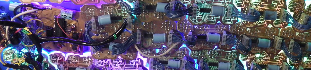
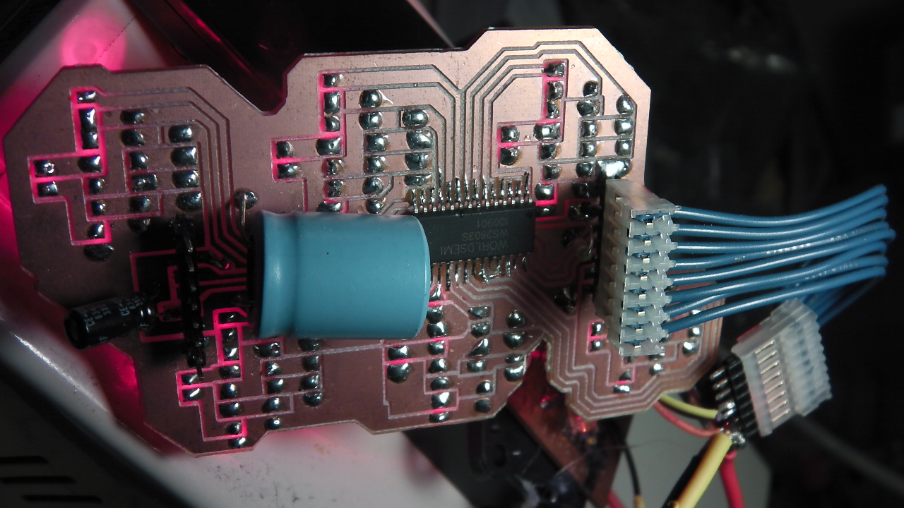
The board uses WS2803 LED driver chips. A WS2803 can drive 18 PWM channels up to 30 volts (6 R,G,B channels). To make sourcing parts easy I’ll use a 12v car/rv/boat battery, so each cell needs to run at 12v. This means 3 3v Blue in series, 3, 3v green in series, and 4,2v red in series. This means 9-10v per series group. If I go all the way to 12v the LEDs won’t work when the battery goes down to 11.9v due to the low operating voltage range of LEDs.

I CNC’d and populated the circuit boards the next day. They work very well.
This project calls for 121 of the circuuit boards, so I’ve spend the last two weekends running the CNC machine and soldering.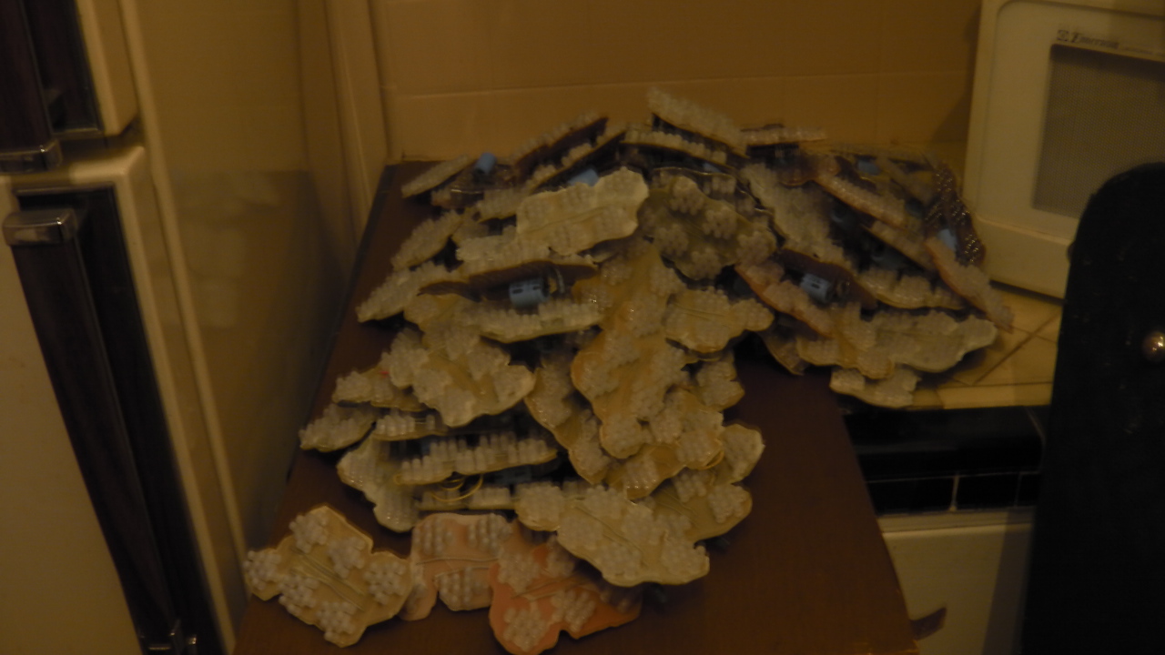
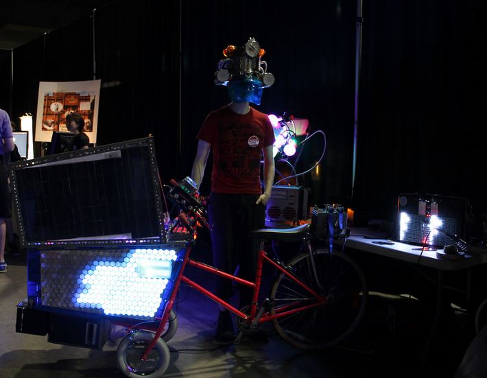
I really need to update this blog since a bunch of people at Vancouver Maker Faire took home business cards with rkproject.net on them. This is the shopping cart rave tricycle I was showing off.
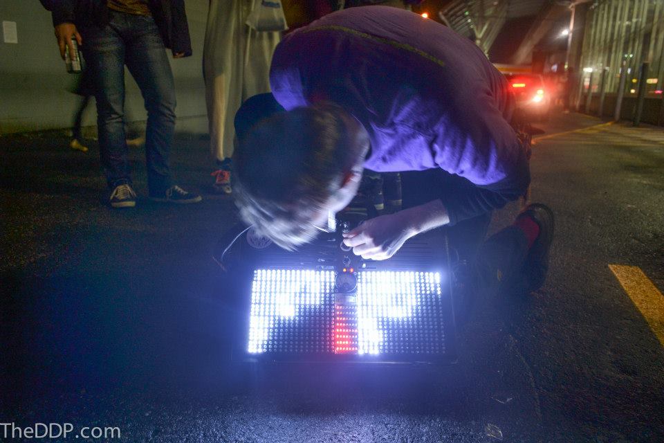
My briefcase boombox with equiliser display isn’t 100% complete yet but I decided to take it out to a party. Nobody noticed that some of the control knobs and sliders didn’t do anything yet. The event was Tom And Gary’s NYE Decentralized Dance Party. About 100 people and boomboxes showed up at a Skytrain station. Tom brought a power glove controlled pirate FM transmitter to broadcast audio to the boomboxes. We wandered around downtown for a while, took a skytrain to the airport, and made the newspaper.
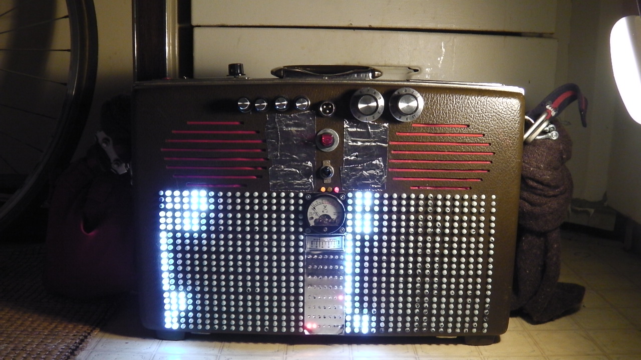
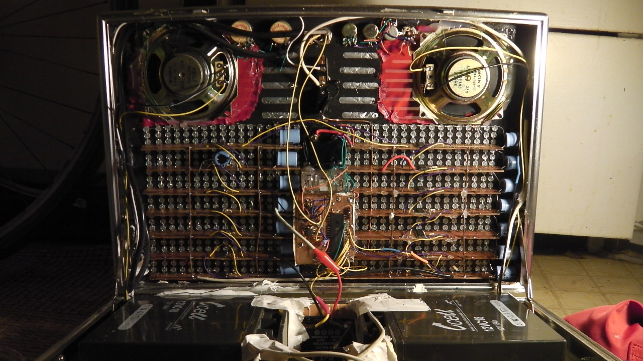
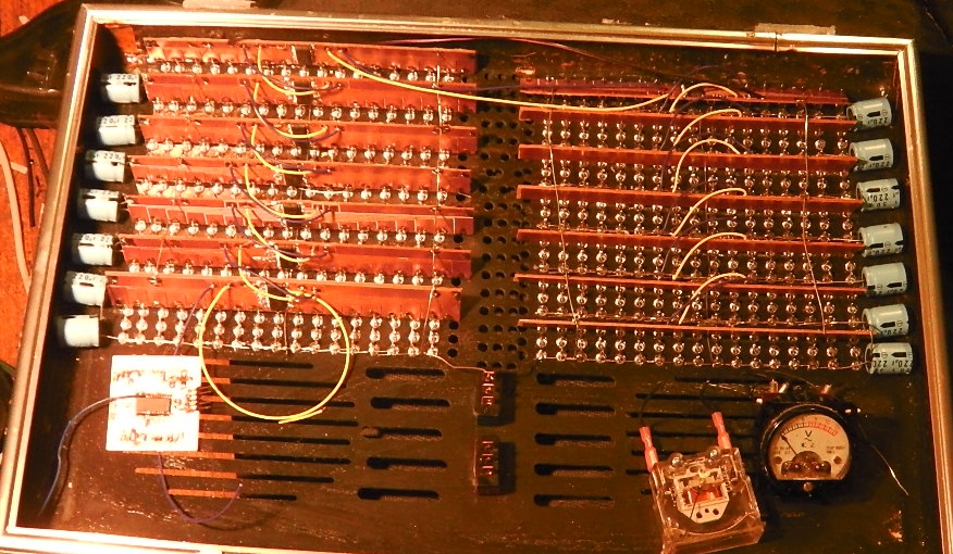
Progress on the Equalizer LED Briefcase:
Speakers are installed. I’m using a pair of full range 4″ 30W RMS speakers salvaged from a broken stereo. They’re not a perfect match for the ovoid vent holes I cut for speakers, but some stretched red fabric hides it.
Batteries are installed. I’m using a pair of 12v 18Ah SLA batteries. Given the system’s average current draw of three amps this will last 12 hours. This is certainly overkill but with this much power to spare I can plug other equipment into the briefcase (very useful). It’s really heavy though. I might decide to take one of them out.
I decided to replace the PIC18F2620 with a PIC18F4550. Mostly because the little 2620 didn’t have a lot of IO pins and I didn’t want to go through the mess of trying to expand it with shift registers or latches.
I still need to finish the analog equalizer control system. The horizontal slots on the near the center top are for slide potentiometers to be used in this system.
There are also a few potentiometers that don’t go to anything. They will eventually run to the microcontroller ADC and used as inputs to control LED brightness, as well as the hysteresis and sensitivity of the audio response system.
I found a very nice looking old briefcase at a thrift store today. I’ve decided to turn it into a boombox briefcase with an LED equalizer display as well as a pair of galvos and other assorted bells and whistles. So far I’ve built some boards, CNC’d the briefcase, and started placing components.
The system is going to run off 12v because that’s the most common for stereo amp boards.
There are fourteen equalizer boards split into left and right. Each bar has seventeen stages. Each stage is made up of three 5mm 3v 20mA frosted white LEDs in series. LED bars are driven by WS2803 chips on some boards I’ve cut and mounted at 90 degree angles. Audio processing will be done by a pair of MSGEQ7 chips. A PIC18F2620 reads their values through its ADC and controls the WS2803s through SPI.
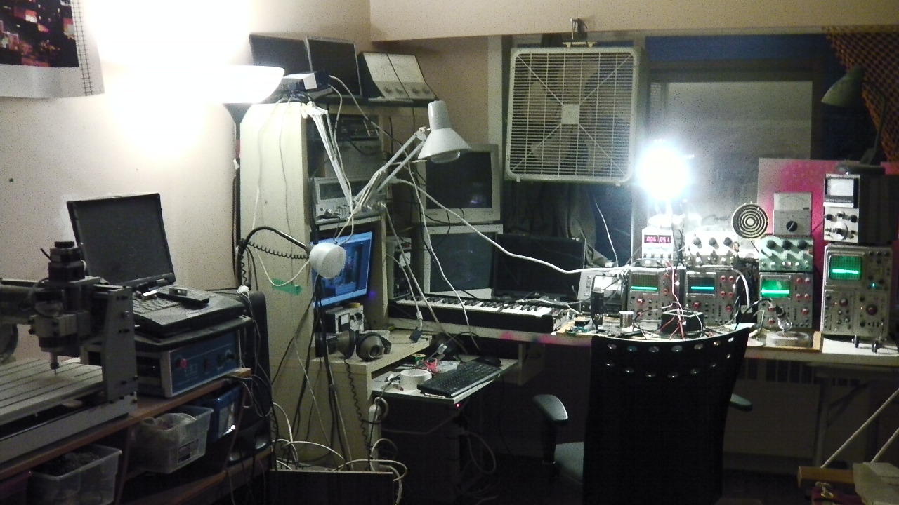
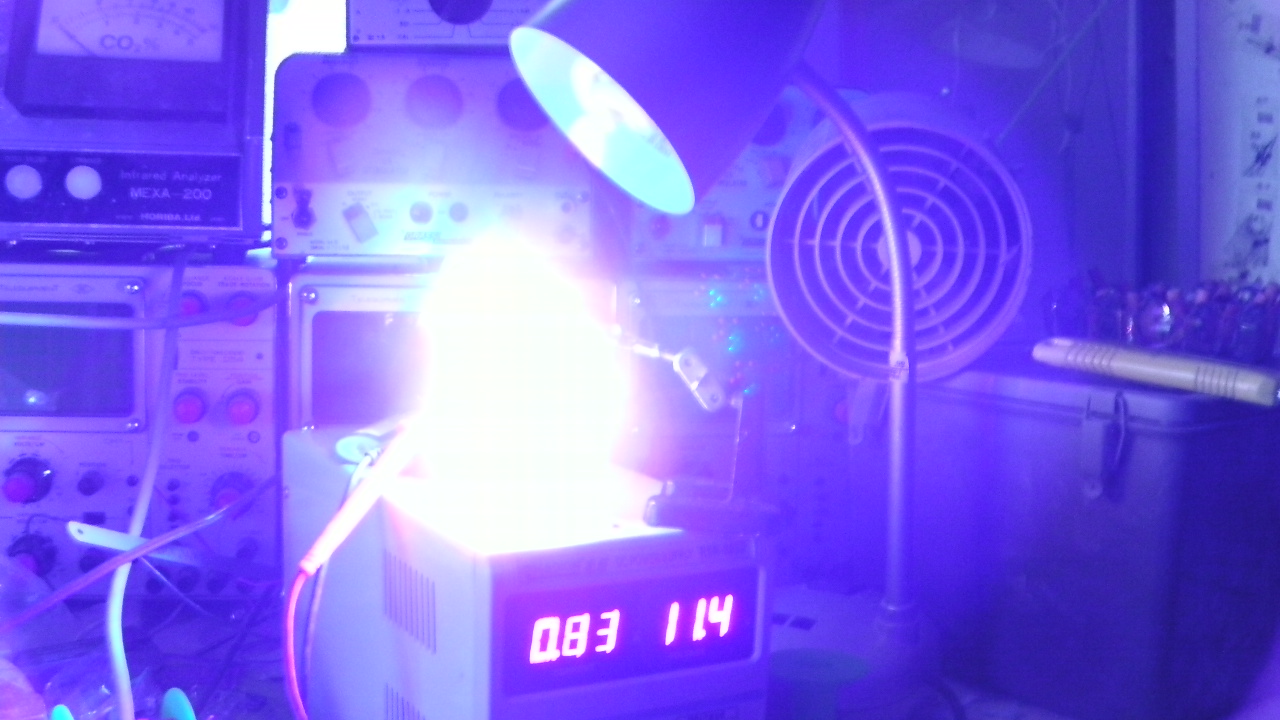
This is the old Vancouver laboratory I’ve just moved out of. Still in the process of setting up in my new place. Hopefully with fewer scattered wires. Hammock in the bottom right corner. CNC machine to the left.
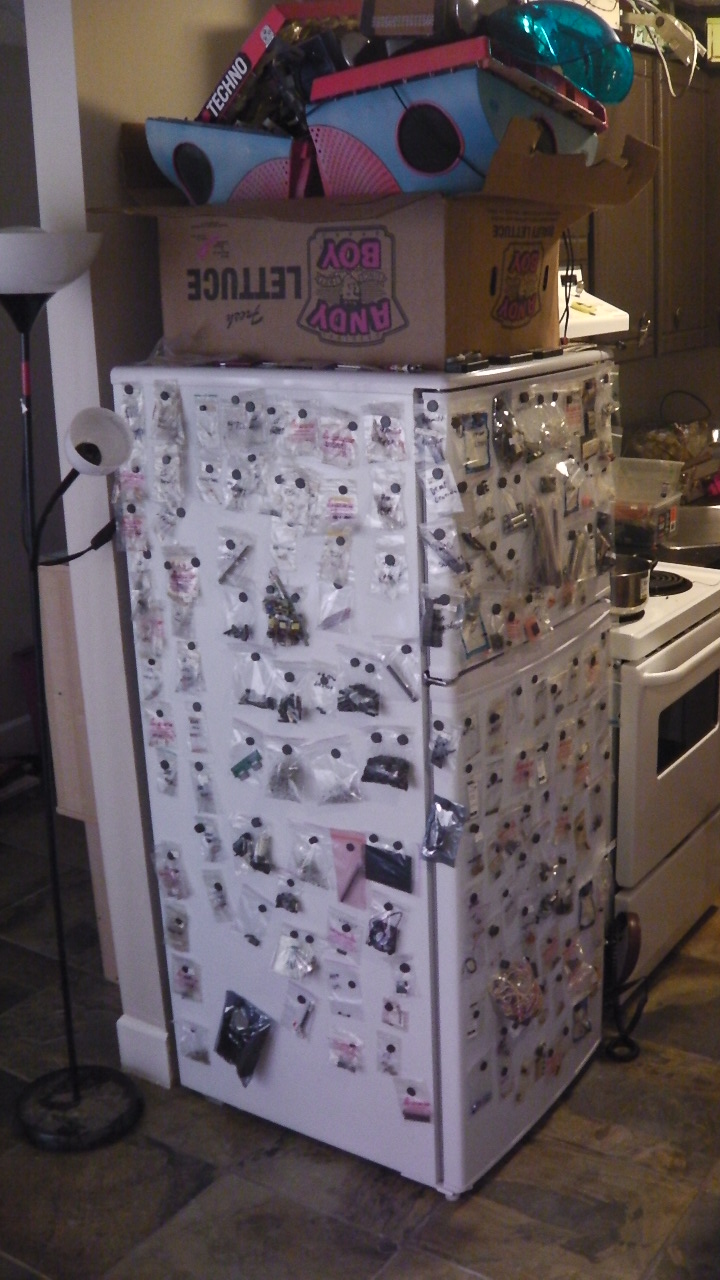
I moved into a new apartment today, and this one has a fridge. While packing up the old laboratory I realized I own hundreds of little bags of electronic components in random junk boxes. As soon as I got to my new place I decided to get them organised. This was the result.
I’ve tried using those racks of small boxes for organizing parts like this, but pretty quickly most boxes contain items that don’t match the label I wrote on them. I think this is a much simpler and easier to maintain system. Resistors and capacitors are in grids with first digit assigning the column and ascending value assigning the row. ICs, connectors, and everything else are spread out fairly randomly in the remaining space.
